![]() Ballast Inductor Characteristics
Ballast Inductor Characteristics
This section is concerned with the technical specification and testing of these ballasting inductors.
|
|
Dimensions: |
250(h) 180(w) 160(d) |
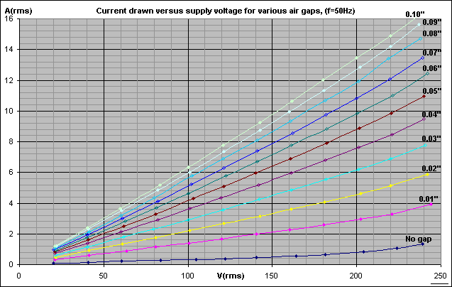
After taking delivery of the inductors, each one was connected across the output of a variac to test for correct current limiting action. The graph below shows the AC current passed by the ballast inductor at different supply voltages. The inductors were initially tested with a variety of air gaps from zero (no gap) to a tenth of an inch (2.5mm). Each coloured line shows the current passed by the inductor with a particular gap setting.

Notice that there is little sign of saturation at the high voltage end of the graph. The bottom line (no gap) is perhaps the only line which noticeably "turns-up" at the right. This is to be expected since the lack of air-gap increases the flux density in the core taking it nearer to saturation. As the air gap is increased, the current increases, but the likelihood of saturation diminishes. Also notice that there is a wide range of current control to be had by simply adjusting the air gap.
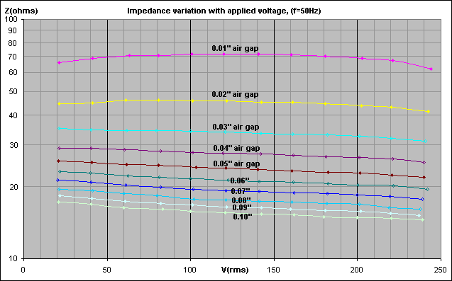
The graph below was obtained by dividing the applied voltage by the inductor current. It shows how the impedance of the ballast inductor changes with applied voltage. The coloured lines show the impedance of the inductor with various gap settings. (The "no-gap" line is not visible on this graph.)

An ideal inductor would have a constant impedance regardless of the applied voltage. However, in practice the steel core does not magnetise in a linear manner and there is a small drop in the inductance as the applied voltage is increased. As more domains are magnetised, less domains are available to be magnetised and the permeability of the core drops. In Tesla coil service this is of little concern, and the average impedance can be used for calculations. Any saturation of the core would be clearly visible on this graph as a sharp drop in impedance towards the high voltage end of the graph.
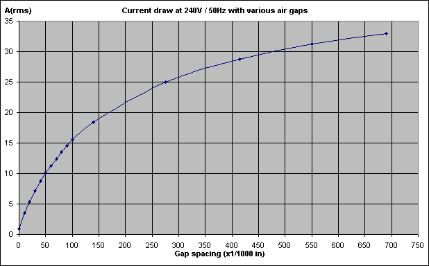
The graph below shows the current drawn from 240V / 50Hz with various different sizes of air gap.

The current range of 1A to 33A equates to a VA range of 240VA to 8kVA. This is quite a wide range of control for a single inductor. However, it means that each unit is universal and can be put into service in Tesla Coil systems of all sizes.
From the graph it can be seen that the current rises more slowly at the high current end of the scale where the air gap is greatest. This is because the influence of the I-block diminishes as it is moved further from the E-core. The magnetic flux lines from the E-core start to take a "short-cut" through the air instead of reaching the I-block. A maximum current of 40 Amps is achieved with the I-block completely removed.
When I did a prolonged test at 35Arms, the warmest part of the inductors was not the windings or the core, but the top corners of the four angled sections that hold the laminations together. Only the extreme top corners were noticeably warm, whilst the rest of the angle-iron sections remained as cold as the core ! I have recently been informed that this is due to fringing flux which leaves the iron core at the air gap.
Unlike a transformer, this type of ballast inductor tends to "leak" its magnetic field into the surrounding air due to the inclusion of the air gap. One needs to be cautious if fitting such an inductor into a metallic enclosure, as the stray fields cause eddy currents to be induced in nearby metal. The circulating currents can cause considerable heating and even blistered paint on the walls of the enclosure !
![]() Results when put into Tesla Coil service
Results when put into Tesla Coil service
These inductors have been used to ballast both Alan Sharp's and Mike Tucknott's big Tesla Coils at previous UK Teslathons. In both cases they were found to be more efficient than the use of MOTs or arc welding supplies for ballasting. With one ballast spark lengths of 8 to 10 feet were easily maintained with no noticeable heating or saturation of the inductor.
One of these ballast inductors has also been put into service on my 4" demo coil. The coil produces regular 6ft strikes, and operation is very smooth and free from any surging.