Telsa coil components continued…
 Multiple static spark gap (TCBOR gap,)
|
|
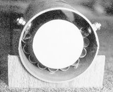
With the exception of the triggered static gap, most static gaps fire naturally due to overvoltage breakdown. The picture on the left shows a multiple static spark gap, made up of several smaller spark gaps connected in series. The multiple gap is constructed from several parallel copper tube sections, with 0.5mm air gaps between them. The electrodes are mounted on a central plastic tube, and are surrounded by another plastic tube at the outside. Fans are fitted at both ends of the enclosure to provide a high flow rate of fresh air during operation. This cools the electrodes and removes hot ionised gases from the spark gaps, improving performance considerably.
|
|

|
The required breakdown voltage is selected by "tapping" at the appropriate number of gap sections. More gaps in series gives a higher breakdown voltage.
This spark gap is often incorrectly referred to as an RQ-gap but was originally developed by the Tesla Coil builders of Richmond group. It performs well up to power levels of around 2kW. Above this level cooling and electrode erosion become problematic.
|
Operation of the static gap in a Tesla Coil is described in the section on Static Gap Analysis.
200BPS Synchronous Rotary gap,
|
|
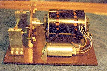
This picture shows my synchronous rotary spark gap. It makes use of an induction motor which has been modified for salient pole operation.
The rotary disc spins at 1500 RPM and contains eight zirconiated Tungsten electrodes. There are two fixed electrodes also made from 1/8" zirconiated Tungsten. This results in a firing rate of 200BPS.
The motor is mounted in a cradle which allows full adjustment of the rotary firing position relative to the AC supply waveform.
|
|
|
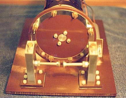
Flying electrodes are mounted in the Phenolic disc by means of brass electrode holders, and are connected together by a silver plated aluminium ring.
Fixed electrodes are connected to aluminium blocks by means of brass electrode holders. The Al blocks provide support and add thermal mass to aid cooling of the stationary electrodes. They also act as terminal posts for the electrical connections to the power supply and primary tank components.
A safety gap consisting of two rounded carriage bolts can be seen in the foreground between the two Aluminium blocks.
|
|
|
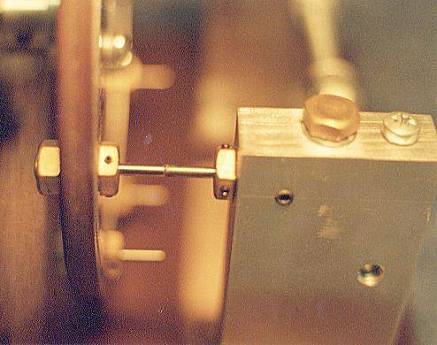
Electrode holders are M8x16 brass bolts with the faces drilled to accept 1/8" tungsten rod to a depth of 13mm. Two side faces of the head are drilled and tapped to take M2.5 set-screws. This mounting method permits the electrodes to be moved back and forth in the holders and then locked in place using the grub-screws.
This allows electrode tip runout to be minimised, and also makes gapping and electrode replacement easy.
The air gap between the stationary and rotating electrodes is 0.5mm +/- 0.2mm.
|
Operation of the rotary spark gap is described in more detail in the rotary gap sections.
Ballast,
|
|
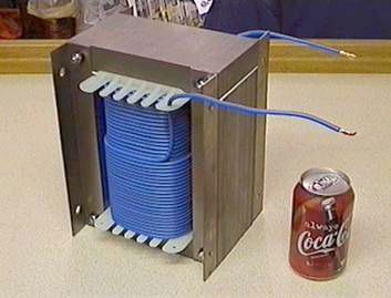
This picture shows one of my current limiting inductors. Each inductor measures 10" x 7" x 7" and weighs-in at a shade under 30kg.
The inductor is connected in series with the LV primary winding of a power transformer in order to limit the maximum current drawn from the mains supply, and to control the capacitor charging.
Each inductor is variable between 18mH and 800mH. This allows the current to be set at anything from 1A to over 40A rms by adjusting the air gap.
The Cola can gives an indication of scale.
|
|
|
These units were made on request by a commercial transformer manufacturer to ensure high quality and reliability in use. The windings are 6mm² high temperature equipment wire and each unit is rated for continuous duty at 40A rms.
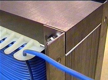
The core is made from high silicon steel laminations and includes an airgap in the magnetic path to prevent saturation. In practice the gap is packed with plastic and can be seen clearly in the picture opposite. Various thicknesses of hard polystyrene sheet are used to obtain the required gap in the magnetic path. This prevents the air-gap from closing due to the extreme force when operating.
|
These ballasting inductors were quite expensive, but have proven a very worthwhile purchase. Their DC resistance is very low and they are highly resistant to saturation. They are considerably more efficient than other forms of ballasting such as NSTs and MOTs, and are not plagued with overheating and run-time limitations found with arc welding sets. In summary, a gapped E-I inductor provides excellent efficiency with a high degree of flexibility, and represents the method of choice for ballasting medium to large Tesla Coil power supplies.
Click here to see more technical information, including V/I characteristics for this ballast inductor with different air gaps.
The function of ballast in a TC supply is explained here.
Toroid,
|
|
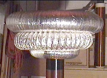
The metal toroid of a Tesla coil system sits on top of the secondary coil and provides the last point from which the electricity "jumps-off" into the air.
This shape is often formed by bending ventilation ducting into a circle, however a more professional appearance can be achieved by using metal spinning techniques on a lathe.
|
A correctly sized and positioned toroid provides several useful functions:
The toroid adds capacitance to the "open end" of the secondary coil.
The toroid provides electrostatic shielding of the top turns of the secondary winding.
The toroid provides a local store of charge to fuel spark propagation.
Once the air surrounding the toroid has broken down it requires charge to drive the streamers out to great length. Since the secondary is highly inductive, it does not represent an instantaneous source of current to any arcs emitted from the top. Even the self-capacitance of the secondary is distributed, so only a limited amount of this stored energy is available to feed sparks. The addition of a large toroid provides local energy storage at the top of the secondary. The capacitance of the toroid should swamp the distributed capacitance of the secondary so that most of the energy is stored in the terminal capacity and little is trapped in the distributed capacitance of the resonator.
Arcs to ground are visibly more intense when a large toroid is used to provide considerable terminal capacity.
The toroid forms a smooth surface to delay the onset of air breakdown.
The effectiveness of a given toroid depends on the system in which it is operated. Generally, small toroids with rough surfaces produce many short arcs. In contrast toroids which are physically large and have a very smooth finish perform better by forming only one longer arc.
The overall size of the toroid (major dimension) determines the capacitance of the terminal. The larger the toroid, the more capacitance it has, enabling it to store more energy. However, remember that the peak voltage actually decreases as the toroid is made bigger !
The thickness of the toroid (minor dimension) determines the radius of curvature. It is this dimension that influences the voltage at which the toroid will breakout. Fat toroids have a higher radius of curvature, and require a high voltage to cause break out, whereas a thin toroid will break out at a much reduced voltage.
It is easily possible to make a toroid so large and smooth that spark breakout is suppressed completely. In this case, a "breakout point" can be placed on the surface of the toroid to produce a localised field stress and promote breakout in that region. I have found this approach successful in producing the longest arc possible from a given power.
Three toroids were stacked on top of each other in the picture above. This was done to add considerable capacitance to the secondary and drop its resonant frequency to a low value. This in turn allows a large primary capacitor to be used to maximise power delivered to the primary. From this explanation it can be seen that the choice of toroid is very important, and can influence other aspects of the design right back to the primary capacitor and even the power source !
There is considerable discussion on the subject of "correct toroid sizing" in the Pupman Tesla list archives.
Primary Coil,
|
|
The primary coil and primary capacitor form the primary tank circuit. This parallel resonant circuit is responsible for the generation of RF oscillations in the Tesla Coil system every time the spark gap fires.
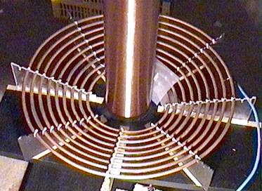
The primary coil pictured opposite is an inclined spiral wound from 1/4" (6.4mm) soft copper tubing. The most effective number of turns, spacing and geometry are dependant on the design of the overall system.
In particular the resonant frequency and Q of the primary tank circuit are influenced by the construction of the primary coil.
|
There are several aspects of the primary coil worth consideration at the design stage:
- High current capability,
The peak currents in the primary circuit are tremendous when the spark gap fires and the tank capacitor is discharged into the primary coil. In a small TC the peak primary current may be around 100A, and in a large system the peak current may be several thousands of amps ! The actual peak current is dependant on the primary voltage and surge impedance of the primary circuit, (see below.)
The high peak current means that the primary coil should be constructed from a good electrical conductor with low resistivity and considerable cross-sectional area. This keeps resistance low and minimises I²R losses.
- Skin effect,
Skin effect discourages AC currents from flowing deep inside good conductors. This means that if you use a good conductor for your primary, then the heavy primary currents are forced to flow in a thinner layer nearer the surface of the conductor. The bulk of the conductor contributes little to AC conduction, but does help in the conduction of heat. For these reasons, copper tube is a popular choice for primary coils. It represents a good compromise between conductivity and ease of forming into the desired shape.
- Adjustable inductance,
For a Tesla Coil to operate correctly the primary and secondary circuits need to be tuned to the same resonant frequency. This can be achieved by making one component of either the primary or the secondary circuit adjustable. In a TC the resonant frequency of the secondary is usually "fixed" at the design stage, therefore the primary frequency must be made adjustable to allow accurate tuning. The simplest way to achieve this is by making the primary inductance adjustable by means of a moveable tap point. This allows the required number of primary turns to be selected to get the desired resonant frequency.
Fp = 1 / [2 pi sqrt (Lp Cp)]
The moveable tap connection should consist of a clamp with considerable force and surface area in contact with the primary winding to minimise resistance in light of the high currents mentioned above.
- Loose coupling to the secondary,
For correct energy transfer in a two coil system the magnetic coupling between the primary coil and the secondary coil is fairly low or "loose". (k<0.2) The exact coupling factor depends on the system, but can be heavily influenced at the design stage. For example, a vertical helix primary which covers a considerable part of the secondary will give a very high coupling factor, whereas a flat spiral at the base of the secondary gives a comparatively low coupling factor.
After the design stage, the coupling factor can be adjusted slightly by altering the relative positioning of the primary and secondary coils. Raising the primary coil relative to the secondary will increase k, whereas lowering the primary coil causes a small decrease in coupling. Coupling factor is explained in more detail in the section on Tesla Coil operation.
- High voltage clearance,
There are three clearance issues to consider with the primary winding. Firstly, the primary winding must be able to withstand the peak primary voltage across the number of turns which are utilised. Peak primary voltages may be quite high, but are usually applied over several turns of the primary coil. This means that the voltage difference between adjacent turns is quite low. Many turns can be packed into a small space to get maximum inductance with minimum length of conductor. The exception to this would be a very high primary voltage applied across a small number of closely spaced turns. This situation may require attention to be given to inter-turn insulation.
Secondly, there is autotransformer action in the primary winding as the primary tap point is moved to select the required inductance. For this reason, the fixed connection is usually made to the innermost end of the primary coil, and the adjustable tap is located near to the outermost end. Care should be exercised when utilising few turns of a multi-turn primary, as autotransformer action can result in considerable voltage at the "open-end" of the primary. This is likely to flash over to any nearby metalwork, such as a strike rail.
Thirdly, there is clearance between the primary coil and the discharge toroid on top of the secondary. The relative positioning of the primary and secondary coils is dictated by the coupling requirement mentioned above. For this reason the clearance from primary to toroid is mainly dependant on the length of the secondary coil and should be influenced by the anticipated spark length.
- Surge impedance,
From the equation in section 3 above, it can be seen that a particular resonant frequency can be achieved with many different combinations of Lp and Cp. However, the inductance of the primary winding not only influences the resonant frequency of the primary, but also affects a property called surge impedance. Surge impedance is a parameter used to determine the response of an LC circuit to step changes in the circuit. It is particularly useful in predicting the peak current which occurs in the primary circuit when the spark gap fires.
It is fairly intuitive that using a single turn primary winding would give rise to higher peak currents than using a multi-turn primary, but the degree of this affect is not immediately obvious.
The primary surge impedance is related to the primary capacitor and the primary inductor by the following equation:
Zp = sqrt (Lp / Cp)
Zp represents the effective impedance of the LC circuit to the flow of current when the spark gap fires and the capacitor dumps its charge into the primary winding. The peak primary current can be found by dividing the "fully charged" capacitor voltage by the surge impedance. This gives an indication of the peak current that the spark gap and primary components will be subjected to:
Ipk = Vp / Zp
It can be seen that a specific resonant frequency can be achieved by keeping the product Lp Cp constant, but the surge impedance can be altered independently by changing the ratio of Lp / Cp.
For example, doubling Lp and halving Cp in a given system, would leave the resonant frequency unchanged, but would double the surge impedance of the primary system. The result is a 50% reduction is the primary current which flows through the spark gap. Since the gap represents a constant voltage drop, this implies a 50% reduction in power dissipation in the spark gap.
In general primary surge impedance should be high (several tens of ohms) when compared to the resistance of the spark gap during conduction. This ensures that the majority of the energy from the tank capacitor is processed through the primary tank circuit, and minimal energy is "burned-up" in the spark gap. Ultimately, there is a tradeoff against output voltage if too many primary turns are used.
The following sections will be completed when time permits…
Secondary Coil,
Line Filter,
Variac,
|
|
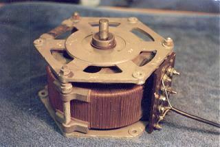
The picture opposite shows a 240V 15A variac for use with a 50Hz supply. The output voltage is variable from 0 to 275 volts.
A variac is very useful in a Tesla Coil system because it allows the user to vary the supply voltage manually and therefore control the power level. During initial testing the power level can be increased slowly whilst looking for any abnormal behaviour.
Due to the large thermal mass of the iron core and windings, variacs generally tolerate moderate overloads well. Twice the rated current for a couple of minutes presents no problem provided that the device is allowed to cool before it is operated again.
|
RF Ground,
Wiring,
 Back to home page