Tesla Coil power supplies require some form of current limiting or ballast in order to achieve the following objectives:-
|
|
Neon sign transformers have built-in magnetic shunts which give current limiting. In its intended use as a supply for neon tube, the high open circuit voltage of the transformer is used to strike an arc in the neon tube. Once an arc has formed inside the neon tube, the current must be limited to prevent overheating of the neon tube and the transformer due to excessive current flow. (The hotter the arc gets, the more current flows, so it gets hotter etc…) The magnetic shunts in the neon sign transformer effectively introduce inductance in series with the leads to the transformer. This inductance is known as the leakage inductance of the transformer as it is a property which is deliberately introduced when the transformer is being designed.
|
|
POWER TRANFORMER
|
Power transformers are designed with extremely low losses so they require good ballasting to operate safely and achieve good performance in Tesla Coil service. Great detail is paid to minimising Leakage Inductance in power tranformers in order to provide good "Regulation". This regulation is exactly the opposite of what is required in a good Tesla Coil supply. Power transformers can be ballasted using Resistive ballast or Inductive Ballast, or a combination of the two in series. The ballast can be placed in series with either the LV primary winding or in series with the HV secondary winding although the amount required will be different for each case. |
The relative merits of each type of ballast are explained below.
The easiest way to limit current is to introduce resistance in series with the load. In a Tesla Coil supply, current can be limited by adding resistance in series with either the LV feed to the primary of the transformer or in series with the high voltage secondary of the transformer.
|
|
If a resistance is connected in series with the primary feed to the step-up transformer the maximum current flow occurs if the HV output is short circuited. If the transformer is assumed to be ideal then the short circuit at the HV secondary is "reflected" back to the primary and appears as if there is also a short across the LV primary of the power transformer. |
|
|
Since the primary appears shorted the circuit can be simplified as shown. The current drawn from the LV supply line is found by using ohms law: |
|
|
If the transformation ratio of the transformer is known, the short circuit current at the HV secondary of the transformer can be calculated. Since voltage is transformed upwards by 1:n from the primary to secondary, the current is therefore transformed down by n:1 from primary to secondary to keep power equal. Therefore: HV current = LV current / n |
The example above shows the ballast resistance connected in series with the primary of the transformer although a resistance could be used on the secondary side instead. The operation is exactly the same however a different resistance is required because the current is lower and the voltage is higher on the secondary side compared to the primary. In order to get the same current flow the secondary ballast needs to have a resistance which is n² times that required for the primary.
Secondary ballast resistance = n² x Primary ballast resistance
If you don't believe me here is the proof.
Below are two examples of a supply ballasted to 960va using first primary then secondary resistive ballasting.
|
Primary ballasting,
|
The short circuit on the HV secondary appears as a short at the primary and the 60ohm resistor limits the current to 4A(rms) on the LV primary side. The current on the HV secondary side is 80mA(rms) because of the 1:50 transformation ratio of the transformer. |
|
Secondary ballasting,
|
The 240v supply is applied directly to the transformer primary, and 12kv develops across the secondary winding due to the 1:50 transformation ratio. The current on the HV side is limited to 80mA(rms) because of the 150kohm resistive ballast. The current on the secondary is transformed up by the transformation ratio to give a primary current of 4 amps, (the same as above.) Power dissipation in the resistor is also 960va, but this time the transformer is operating at its full rated voltage. |
Neither primary or secondary ballasting is any more efficient, and they are actually equivalent. However there are some differences between them which are worth considering:-
|
Primary Resistive ballasting |
Secondary Resistive ballasting |
|
|
|
|
|
|
|
|
|
|
Properties of Resistive Ballast,
The major disadvantage of resistive ballast is in the way in which it actually limits the current flow : By dissipating excess power as HEAT. It is apparent from the examples above that when the ballasted supply is short circuited the full power rating of the supply is dissipated in the resistive ballast as real power. It is also apparent that when the ballasted supply has no load connected to the HV output then no power is being dissipated in the ballast. But what happens when a real load is connected to the output of the supply ?
|
|
If a variable resistive load is connected to the output of a resistively ballasted supply, then power is dissipated in both the ballast and in the load. The proportion of power being dissipated in each depends on the actual ballast resistance Rb and the load resistance values.
|
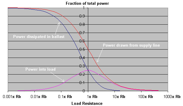
The graph below shows the power dissipated in the resistive ballast, and in the actual load for various different load resistances. (The total power drawn from the supply line is the sum of the two power dissipations.)

At the far left of the graph where the load resistance is far smaller than the ballast resistance (Rb), a large amount of real power is drawn from the supply but almost all of it is dissipated in the ballast. Little power is dissipated in the load.
In the middle of the graph where the load resistance is equal to the Rb, the power drawn from the supply has dropped to 50% of the short-circuit value and this power is split equally between the ballast resistance and the load itself. At this point where Rload = Rballast the maximum power is transferred to the load. This is known as impedance matching.
At the far right of the graph where the load resistance is much higher than Rb, the power drawn from the supply drops away to zero although what little power is drawn goes mostly into the load.
The equivalent impedance matching graph for inductive ballasting is shown in the section on inductive ballasting below.
In summary, with resistive ballast the maximum power that can be delivered to the load is 25% of the short circuit power and an equal amount of power is being wasted as heat in the ballast at the same time. In addition to this problem, resistive ballasting lacks some of the other desirable features which inductive ballasting offers. In the favour of resistive ballasting is the fact that it will not saturate and it does not introduce a time lag like inductive ballast can. Resistive ballast systems may also be cheaper and easier to design and test. The major disadvantages are heat generation and poor efficiency.
An HV supply can be current limited by adding any impedance in series with either the primary or secondary. This impedance does not have to be resistive, and there are many advantages which can be gained from making it reactive.
|
|
If an inductor is connected in series with the feed to the primary of a step-up transformer, the short-circuit current will be limited. If the HV secondary output is shorted the short circuit is reflected back to the primary winding and it appears as though the primary were also shorted.
|
|
|
Since the primary appears shorted the circuit can be simplified as shown. The current drawn from the LV supply line is found by using ohms law, but we must first calculate the impedance of the ballast inductor at the supply frequency. Z = 2 * pi * F * L then LV current = LV supply voltage / Z An inductive ballast can be checked for correct operation by direct connection to the supply line as shown, without the HV transformer in circuit.
|
|
|
If the transformation ratio of the transformer is known, then the short circuit current at the HV secondary of the transformer can be calculated. Since voltage is transformed upwards by 1:n from the primary to secondary, the current is therefore transformed down by n:1 from primary to secondary to keep power equal. Therefore: HV current = LV current / n |
The example above shows the ballast inductor connected in series with the primary of the transformer although an inductor could be used on the secondary side instead. Alternatively leakage inductance can be built into the transformer during design, as is common with Neon Sign Transformers and Microwave Oven Transformers. The operation is exactly the same regardless of whether the ballast inductor is on the primary or secondary side of the transformer, however a different inductance is required because the current is lower and the voltage is higher on the secondary side compared to the primary. In order to get the same current flow the secondary ballast needs to have an impedance which is n² times higher than the primary ballast would need to be. This is easily achieved by multiplying the required inductance by n².
Secondary ballast inductance = n² x Primary ballast inductance
If you don't believe me, the proof is given above in the section on resistive ballasting. Everything is the same except for the bit about dissipation in the ballast. Inductors do not limit current in the same way as resistors, they do not dissipate the excess power.
Neither primary nor secondary ballasting is any more efficient than the other if they are both designed carefully. However there are some differences worth considering:-
|
Primary Inductive ballasting |
Secondary Resistive ballasting |
|
|
|
|
|
|
|
|
|
|
Properties of Inductive Ballast,
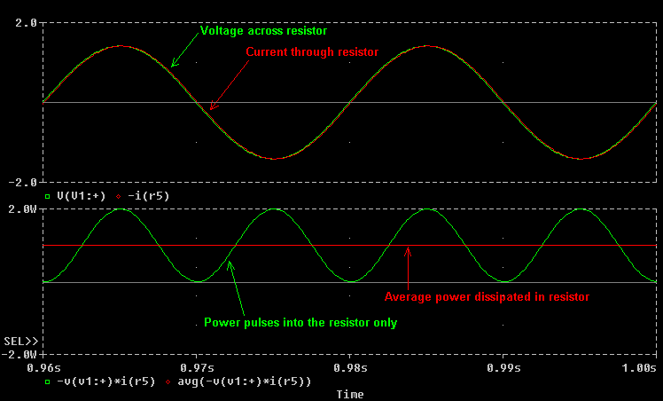
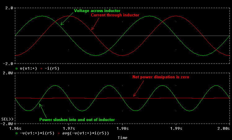
The main advantage of inductive ballast comes from the way in which inductors limit current. An inductor can be chosen to have the same impedance as a given resistor, but when the inductor is connected to a voltage source there is a subtle difference in the current which flows.
In the case of the resistor, the current and voltage are in phase and the power pulses into the resistor only. The average power line (in RED) indicates a net flow of power into the resistor.

In the case of the inductor, the current is out of phase with the applied voltage and lags by 90 degrees. Reactive power sloshes in and out of the inductor at 100Hz but the net power flow is zero. Assuming the inductor has zero resistance, no real power will be dissipated and therefore there will be no heating due to dissipation.

This means that when an inductively ballasted supply is shorted it will draw current from the line cord which is out of phase with the voltage. An Ammeter will still register the current being drawn, but a Wattmeter indicates no power flow as expected. So if an inductive ballast dissipates no power when the supply is short circuited what happens when a variable resistive load is connected to the supply ?
|
|
When a variable load is connected to the output of an inductively ballasted supply, then the amount of power dissipated in the load depends on the actual values of the inductor and the load resistance. However no power is ever dissipated in the inductor (assuming zero winding resistance.)
|
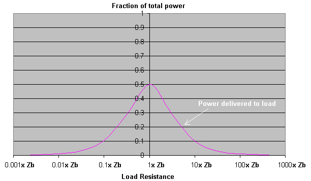
The graph below shows the power dissipated in the load for various different load resistances. (The total power drawn from the supply is the same as the load power as the ballast consumes no power, although the phase of the current and the power factor will vary.)

At the far left of the graph where the load resistance is far smaller than the ballast impedance (Zb), no real power is drawn from the supply although there will be considerable out-of-phase current. No power is delivered to the load.
In the middle of the graph where the load resistance is equal to the Zb, the real power drawn from the supply peaks and up to 50% of the short-circuit value is supplied to the load. At this point where Rload = Rballast the maximum power is transferred to the load. This is known as impedance matching.
At the far right of the graph where the load resistance is much higher than Zb, the real power drawn from the supply drops away to zero and the power to the load also drops to zero. There is little current drawn from the supply line here.
When compared to the resistive ballast graph, this indicates a 100% increase in power to the load. The power which was previously dissipated in the resistive ballast now goes into the load as well, giving increased performance.
The energy storage ability of the inductive ballast not only minimises power dissipation, but also gives rise to several other effects as the stored energy is released.
All of the discussions about ballasting so far have considered the supply driving current into a short circuit or a resistive load. The situation changes when a Tesla Coil tank capacitor is charged from an inductively ballasted supply. The addition of the capacitor creates a resonant network with the ballast inductor and makes Resonant Charging possible.
When a spark gap is then added to the system, it complicates matters further by causing an Inductive Kick effect to occur. Both Inductive Kick and Resonant Charging are large subjects which are discussed in separate dedicated sections below.
The disadvantages of inductive ballasting are mainly the weight and size of suitably rated inductors, and the fact that inductive ballasting can introduce a time delay. If a large amount of inductance is added into a system with very low stray resistance, the system may become slow to respond to changes in current. This means that if the ballast is adjusted quickly the change will gradually take affect over several seconds. This effect arises because of a time constant formed by the inductance and stray resistance. T = L / R, If L is big and R is very small the time constant can be long enough to cause considerable "time-delay" and prevent smooth operation. Usually the addition of a small amount of series resistance will shorten the time constant drastically without causing too much power dissipation.
Finally, saturation can occur if the ballast inductor is designed incorrectly or if it is overloaded with too much current. Unfortunately saturation can be a run-away phenomena. If the current through the ballast gets too high the iron core will saturate and the value of the inductance drops rapidly. This drop in inductance causes a further increase in current which drives the inductor into hard saturation. Hard saturation results in sharp current spikes at the peaks of the supply cycles as the ballast inductor effectively looses its limiting properties. This situation should be avoided by generously specifying the amount of iron in the ballast inductor, and by including a non-magnetic gap in the iron core to prevent magnetic saturation.
Click here to see a practical primary ballast inductor design.
Take me to the next section on RESONANT CHARGING.