|
Click on a component above, or select from the list below.
|
 Tesla Coil components Tesla Coil components
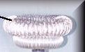
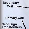
The simplest Tesla Coil consists of only 6 basic parts shown in the photograph on the left:-
The Neon Sign Transformers (shown bottom left) provide the high voltage supply which is required to operate the spark gap.
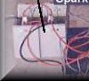
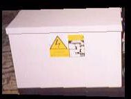
Power from the transformers charges the bank of high voltage capacitors (shown bottom right.)
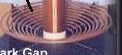
Energy from the capacitors is transferred into the primary winding when the spark gap fires. The spark gap (shown bottom centre) is an RQ style static gap with forced air cooling.
Energy in the primary coil is transferred into the secondary coil by magnetic coupling between the two coils.
When the energy is transferred to the secondary coil it results in an extremely high voltage at the top of the secondary.
The toroid is the last stopping place for the electricity before it jumps into the air.
|
This Tesla Coil is as simple as they get, however there are many additional components which can be added to improve safety, reliability, and performance.
The important properties of each component are discussed below:-
HV Supply Transformer,
There are two types of transformer which are used in Tesla Coil applications. Those with built-in current limiting and those which require external current limiting. Neon transformers and Oil Burner Ignition transformers have built in current limiting and are ideal for direct connection to a Tesla Coil system. However, power distribution transformers and power supply transformers from radio transmitters etc, are examples of transformers which require external current limiting before they can be used successfully in a Tesla Coil system. More details about current limiting are giving in the section on ballasting.
|

|
POWER TRANSFORMER
|
|
Neon sign transformers are available in voltages from around 2kV rms up to a maximum of 15kV. They are designed with output currents of between 8mA and 120mA typically, although several units can be connected in parallel to increase current output capability. Neon sign transformers are usually encapsulated with a solid compound to provide low cost protection.
|
Power transformers come in all shapes and sizes. The one pictured above is a 14kV unit rated at 25kVA designed for power distribution on the supply grid. Power transformers are typically oil filled and are considerably over engineered. This means that they have a lower mortality rate in the harsh Tesla Coil environment. They can often be run past their current rating for short intervals too.
|
The practical limitations imposed on supply voltage and current are as follows:-
Lower voltage limit,
This is limited by the voltage required to make the spark gap fire smoothly. In practice the spark gap electrodes could be set very close together so that only a small voltage is required to initiate breakdown. However, the current is must be increased to maintain sufficient power throughput because of the low voltage. This high current quickly erodes the electrodes and causes clogging of the small gap due to the formation of metal oxides. The coil pictured above uses a 6kV supply and I would not recommend using a lower supply voltage with a static spark gap due to the clogging problem.
Upper voltage limit,
There are many reasons why a high initial supply voltage is desirable. Firstly, it reduces the current required to get a given amount of power, and since most losses are proportional to I² this significantly reduces losses and improves performance. Secondly, energy in the tank capacitor is proportional to V², so using a high supply is a good way to get high energy storage in the tank capacitor. Thirdly, wider spark gaps can be used which tend to run more smoothly without clogging. The upper limit on the supply voltage is usually imposed by the risk of dielectric breakdown of either the transformer itself, or more likely that of the tank capacitor. Above 20kV corona formation starts to become a problem even in some oil filled components, and can quickly degrade insulation leading to failures. The latest coil which I am developing runs with a peak supply voltage of 24kV, and uses an MMC type tank capacitor.
Lower current limit,
The current provided from the supply is responsible for charging the tank capacitor. The minimum current required depends on the size of the capacitor, the amount of time which is allowed for it to charge, and the voltage to which it must charge. In general bigger tank capacitors and faster firing rates demand more current. A system with a small capacitor can give reasonable results with a supply limited to around 15mA, although currents between 100mA and 1A are more common.
Upper current limit,
The upper current limit is imposed by the ability of the spark gap to extinguish. If too much supply current is available the spark gap (shown in the circuit diagram above) becomes overheated and is unable to "switch-off" when the high supply current is flowing through it. Some types of spark gap are better at handling high currents, but in general the maximum supply current is in the hundreds of milliamps range for small to moderate sized Tesla Coil systems.
Primary Tank Capacitor,
The tank capacitor used in a Tesla Coil primary circuit is exposed to possibly the most severe conditions that any capacitor is expected to withstand. A typical tank capacitor will be charged to maybe 20kV in a few milliseconds, then fully discharged into a few feet of copper tube in a few microseconds ! This gives rise to incredibly high peak currents, rapid voltage reversals, and high dielectric stress. The whole process repeats over and over again several hundred times per second.
Because of this harsh treatment the specification and construction of the primary tank capacitor are of great importance if good performance and lifetime are to be achieved. Some important features of the tank capacitor are listed below.
Voltage rating,
The voltage rating of the capacitor must be correct for the system or failure is certain. The voltage seen by the tank capacitor will almost always be much higher than the normal output voltage of the supply transformer, and many things such as resonant rise, inductive kick, and missed firings should be considered when specifying the capacitor. It is very difficult to estimate the voltage seen by the capacitor in a particular design, and computer modelling and simulations are by far the best way to get an idea of the stresses that this capacitor will be subject to without risking damaging any real components. Peak voltages of 3 times the RMS rating of the supply transformer are not uncommon across the tank capacitor.
Dielectric strength,
The capacitor dielectric must be suitably rated for AC use. Even if a DC supply is used to charge the capacitor, there will still be a large polarity reversal as the capacitor discharges into the primary coil. The dielectric of a high voltage capacitor must be a good insulator, and therefore any partial charges which may accumulate inside the dielectric cannot be conducted away. If these partial charges remain in the dielectric when the polarity of the capacitor voltage changes, the dielectric is put under additional stress. This is why it is important to take the polarity reversal into account when choosing a suitable voltage rating.
Peak current rating, (dv/dt)
This is the peak current surge that a capacitor is expected to survive, and will usually be quoted at a specific repetition rate. Peak currents experienced in the primary circuit of a Tesla Coil can range from 100A to over 2000A. If the peak current rating of the tank capacitor is exceeded, it can result in ablation of the metalised connections to the capacitor plates, or gradual errosion of the plates themselves. Both of these effects are highly undesirable. Erosion of the plate material causes changes in the actual capacitance value of the component. Similarly, ablation of the electrical connections to the plates increases the resistance at this point. At high currents this resistance causes further heating, until the connection finally fails open-circuit.
RMS current rating,
This is like the average current that a capacitor can handle without overheating, and is a very important parameter in our application. The RMS current rating is useful because it can be predicted by computer simulations, and it takes into account the peak current, repetition rate, and the duty cycle of the intended use. Typical RMS currents experienced in the primary circuit of a Tesla Coil are between 5A and 100A. If the RMS current rating of a capacitor is exceeded the device will heat up considerably. Mild heating causes thermal expansion and changes the capacitance value of the component. Most capacitors for Telsa Coil service use either Polyethylene or Polypropylene dielectric. Both of these materials soften at temperatures below 100 'C. Excessive heating will reduce the insulating properties of the dielectric and the capacitor will fail.
Low stray resistance,
Since power dissipation is equal to I²R and the discharge current is extremely high, even a small amount of series resistance in the capacitor will result in a large amount of power being dissipated as heat. Suitable pulse discharge capacitors are usually made with Aluminium or Copper plates, and make use of solid connections from the plates to the terminals to minimise series resistance.
Low stray inductance,
Any conductor will have some stray inductance, and the plates of a capacitor are no exception. This inductance would usually be negligible, but if the capacitor is constructed such that the long metal plates are rolled into a cylinder the inductance can become quite high. A high stray inductance in series with the capacitance is undesirable because it limits the peak current that the capacitor can deliver, and also slightly reduces the coupling coefficient of the Tesla Coil as a whole. Series inductance can be minimised by either constructing the tank capacitor from flat stacked plates, or alternatively by using the extended foil method if the capacitor must be rolled. The extended foil method ensures connection along the entire edge of the rolled plates at each end of the roll, meaning that current does not have to travel in a spiral in order to get from one end of the plate to the other. The extended foil connection also ensures a low resistance connection between each plate and the electrical terminals. This is important in light of the high peak currents mentioned earlier.
Low leakage current,
The capacitor dielectric should have a high enough resistance to ensure little current flow at the working voltage. Any leakage current through the capacitor represents power from the supply which is being wasted as heat. Typically leakage current will increase as a capacitor ages. This is because the initial heating effect causes the insulating properties of the dielectric to worsen. This in turn causes an increase in the leakage current, and eventually the dielectric may fail.
Low RF loss dielectric,
Although the tank capacitor is charged at a relatively low frequency, the discharge of the capacitor into the primary circuit results in a high frequency oscillation of typically several hundred killohertz. Therefore the dielectric must be suitable for service at these high frequencies. Polyethylene and Polypropylene are both excellent dielectric materials for Tesla Coil tank capacitors as they exhibit very low RF loss factors and are relatively cheap plastics. Their main disadvantage is their relatively low melting point.
Corona suppression,
At around 5kV corona starts to form in air at the edges of capacitor plates and connections. If this corona is allowed to persist it generates local heating, emits UV light and also produces ozone. Polyethylene dielectric is significantly softened by heating, and it undergoes chemical breakdown in the presence of UV light and ozone ! Corona formation results in slow death as the dielectric gradually deteriorates. Eventually it degrades sufficiently for dielectric breakdown to occur. For these reasons corona formation is the biggest killer of high voltage capacitors, and must be minimised. High voltage capacitors are usually filled with high quality oil to suppress corona, however all remaining air must be carefully removed if corona is to be eliminated. At very high voltages there can still be some corona formation under oil.
In order to work around the voltage and current limitations of a single device, several capacitors are often connected in series and parallel banks. This allows the desired rating to be achieved whilst reducing the stresses seen by any one device. There are 5 main types of capacitor which are commonly used in Tesla Coil applications,
Salt water capacitors,
These use a salt water solution as the "plates" and glass as the dielectric. They are very cheap, but have several disadvantages. Firstly, they give a relatively low capacitance value for their size. Secondly, the glass dielectric exhibits a significant dielectric loss at the high frequencies seen in Tesla Coils. Finally, salt water is not the best conductor to use for the plates of a high current capacitor. Original experiments done by Tesla used this type of construction, although today we have synthetic plastics which make far more efficient dielectrics.
Rolled Aluminium / Polyethylene,
|
|
These capacitors use two long rectangular metal plates, separated by sheets of polyethylene dielectric. The capacitor is then rolled up into a cylinder. This doubles the capacitance as each plate is now next to the opposite plate on both sides. The author has built many rolled polyethylene capacitors for Tesla Coil service, and they perform very well provided they are carefully constructed and filled with oil. Rolled polyethylene capacitors provide a relatively high capacitance value for a given enclosure size, although they still have one significant disadvantage. Home rolled capacitors are not very tolerant of over-voltage events, and do not self heal if the dielectric becomes punctured.
|
Stacked Aluminium / Plastic,
These capacitors are constructed from many squares of aluminium and plastic dielectric, which are sandwiched together to obtain the required capacitance. Connections are made to the plates to form the terminals of the capacitor. The main advantage of this construction method is that it reduces the series inductance because the capacitor plates are not rolled into a spiral. However, the capacitance is often low for a given enclosure size, and construction is very time consuming.
Commercial grade Pulse Capacitor,
Professionally made pulse discharge capacitors are available which make excellent tank capacitors for Tesla Coil applications. The downside is that they are usually very expensive. The construction methods are often similar to those used in the above two examples, however they are manufactured under carefully controlled conditions to prevent contamination and minimise production defects. This is why performance and lifetime are superior to home-made parts. Also, the precise repeatability of the production process allows features like "self-healing" to be incorporated into commercial pulse capacitors, making them more tolerant to abuse.
MMC,
|
|
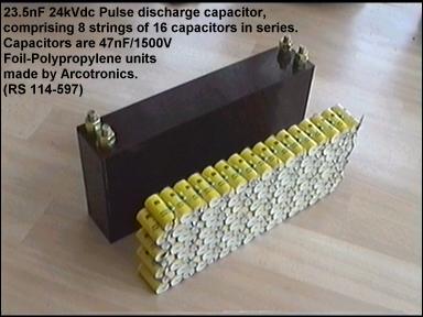
The MMC (Multi-Miniature-Capacitor) consists of many smaller commercial capacitors connected together in a series-parallel array to achieve the required voltage, capacitance, and current ratings. The MMC approach allows Tesla Coil designers to take advantage of the high quality inherent in commercially mass-produced capacitors, without the high cost of a large custom made high voltage device. The MMC approach also means that the voltage stresses are spread across several tens of capacitors. This means that the dielectric in each capacitor is working less hard than it would be if it were the sole dielectric. MMC capacitors are much more tolerant of excessive voltage excursions than rolled poly capacitors if designed correctly.
|
For more information about capacitor types, and construction methods, please see the section containing links to other sites.
Spark Gap,
The spark gap is basically a high power switch. It is the spark gap which is responsible for initiating the discharge of the tank capacitor into the primary winding of the Tesla Coil. It turns-on when sufficient voltage exists across the spark gap. The air in the gap ionises and begins to conduct electricity like a closed switch. The spark gap turns-off when the current flowing through it drops to a low level, and the air gap regains its insulating properties.
When used in this way as a switch, the spark gap has the following properties:-
- High voltage hold-off capability in the off-state,
- High current carrying capability in the on-state,
- Extremely fast turn-on time,
- Physically scalable to almost any power rating,
- Good overload margin, (robust)
All of these properties make the spark gap ideal for the demanding task that a Tesla Coil presents. The main disadvantage of the spark gap as a switch is that it dissipates considerable heat due to conduction losses in the on-state. For serious Tesla coil service there is no alternative to the spark gap switch. Even modern solid state devices do not come close the the pulsed power handling capabilities of the spark gap. (Try finding an IGBT which can switch 30kv @ 500A in under 10ns !)
Spark gap designs are quite varied, but can be categorised as follows:
|
Spark gaps
|
|
Static spark gaps
(no moving parts)
|
|
Rotary spark gaps
(moving parts)
|
|
Single static gap
|
Multiple static gap
|
Triggered static gap
|
|
Asynchronous rotary gap
|
|
Synchronous rotary gap
|
CONTINUED ON NEXT PAGE… <- CLICK HERE
 Back to home page